Cisco RVS4000

A firewall is a bastion of the first layer in this Ethernet router, however the facility Intrusion Detection / Prevention System into second-tier defenses.At first glance, the physical form is very similar to Cisco

D-Link DHP-1320: Access Point Router AND

D-Link introduces the D-Link DHP-1320 Wireless-N Router HomePlug AV with a capacity wireless speeds up to 300Mbps. Having dual operating model, this device can be configured either as a router or access point. In the model of the router, D-Link DHP-1320 is connected to a cable or DSL modem to receive and share your broadband Internet connection with multiple computers, gaming device or media player. In the model access point, D-Link DHP-1320 creates a Wi-Fi connections based on existing networks, effectively expanding the network to overcome blind spots.

Types of Network Cable

affect the price of the cable. Computer Cable Networks can be divided into 3 types, namely Twisted Pair Cable, Coaxial Cable and Fiber Optic Cable. You can use one of these cables in accordance with the needs and budget available.
network cable Macam macam Kabel Jaringan


Computer Cable Networks varying types and types

How it Works OSI


Introduction to Model Open Systems Interconnection (OSI)

Model Open Systems Interconnection (OSI) was created by the International Organization for Standardization (ISO) That Provides a structured framework for logic-how processes Interact via a data communications network. Standards were the resource created for the computer industry to Communicate on different networks efficiently.
OSI Layer Model

osigroupedlayers.gif


the workings of TCP / IP

TCP / IP is a data communication protocol model gives a very large change in the world of communications and computers. TCP / IP protocol is to provide an internationally recognized standard and is used as a reference in the development of the computer world, especially on computer networks. Where this protocol can provide flexibility in communication between one computer with other computers in a network even if the computer uses a different operating system platforms. TCP / IP has five layers. Unlike the OSI model has seven layers. The layers include Physical Layer, Network Access Layer, the Internet Layer, Transport Layer and Application Layer. The fifth layer has the functions and responsibilities of each as well as the existing layer in the OSI model.Chapter

Cable coaxcial and HFC Network Infrastructure

HFC stands for Hybrid Fiber Coax.Saat is the use of HFCs in the telecommunications network gets the most attention karenasecara theoretically allows delivery of various services at once (multiservice) sepertitelephony, internet, cable TV and Video on Demand (VOD) with the promise of higher data transmission speeds high and at an affordable price by pemakai.Dalam race to meet keinginanpelanggan (user) will be Internet service faster and cheaper, a factor that plays an important role is the bandwidth. In comparison, the telephone cable network has low bandwidth, so having a low speed while the HFC network provides a very wide bandwidth that offers a higher speed. This shows great potential for the provision of network-owned multimedia services in real time

Connecting TOOLS AND MEASURE OPTIC

Grafting tools (Fusion Splicer) and measuring tools Fiber Optics (OTDR) is one of the supporting devices in the operational management of the access network Fiber Optics
     For the purposes of Operations and Maintenance (O & M) Network Element that operates using a network acccess Fiber Optics, it is a very important role connecting tools and measuring instruments Fiber Optics. Optical Fiber Access Network as a transport medium for broadband and narrowband services are often susceptible to interference, which formed as a fiber optic cable rupture resulting in Transportation End (Perpu) on the supply terminal equipment and data ports. So to help trouble shooting on Fiber Optic network access control can be done immediately, either in the form of search (searching) the location of cable break penyambunganm Fibre Optic Cable.

Link Tools Fiber Optics (Fusion Splicer)

HFC NETWORKS FOR SINGLE CABLE TELEVISION AND INTERNET

Cable television service and high speed internet has become everyone's needs, especially in big cities. Number of entertainment and information from either the television or the Internet has provided an increasing number of users, so keep in mind the quality, speed and capacity of the distribution of data. For devices that need to be made ​​an advanced technology that can deliver all these services through just one medium that can eliminate the complexity of implementation and use of the device the customer side.

HOW SETTING WIRELESS BULLET

discuss how to apply the settings Bullet 2HP as BTS transmitter that can be received directly by the user's laptop (Access Point) and at the same time using one of the first experience Ubiquiti products.

Following the steps of his setting:

After all devices have been correct installation, connect the UTP cable to the computer via POE mate with a straight connection type and then note the IP address bullet which by default is 192.168.1.20, then set the IP for example 192.168.1.21 pal Lan computer then input the same as the Default Gateway IP Bulletnya .

Super WiFi = Smart Antenna WiFi + Cellular Architecture


Altai Solution

By making use of the smart antenna design and advanced signal processing algorithm, the A8 WiFi base station can effectively provide extended WiFi signal coverage and improved uplink performance, whilst minimizing the interference effect of other signals in the un-licensed frequency spectrum, and yet lower the required capital investment in wireless network infrastructure.

INSTALL SETTING RB 800

Setting Mikrotik Wireless Bridge


Often times, we want to use Mikrotik Wireless for point to point solutions to bridge the network mode (not routing). However, RouterOS itself is designed to work very well in routing mode. We need to do some things so that the wireless link we can work to bridge mode.

HOW TO POST MINI CCTV home

CCTV is now often encountered in every public areas such as malls, campuses, offices, shopping centers and others. The benefits of CCTV themselves will feel useful as a tool for security, where every activity that happens we can monitor live anytime and from anywhere, can also be utilized to record the incident as evidence in future. Maybe you are a business owner who is often lost, for example, may lose a motorcycle, or home robbed but you do not have proof. CCTV in this case can be very helpful. Unfortunately the price and its general CCTV installations for products that * original * price is quite expensive for a service like that. Average cost of CCTV installation generally achieve air-million-million rupiah.

SETTING RB 711

Assemble Homebrew Antenna 2.4GHz

Assemble Homebrew Antenna 2.4GHz "explained as follows,
Omni antenna has a radiation pattern that spreads out in all directions equally, so suitable for use as an antenna access point.


Diagram Antenna Omni Collinear 2.4GHz
 
Diagram Sambungan Antenna Omni 2.4GHz ke Access Point

Hotspot Mikrotik Configuration

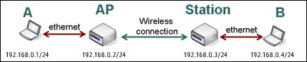
Setting Hotspot on Mikrotik Router OS is very easy to configure. Hotspot authentication system is usually used when we will provide Internet access in public areas, such as: Hotels, cafes, campus, airports, parks, malls etc.. Internet access technologies typically use wireless or wired network.
Usually provide free internet access using the hotspot or can also use the voucher for SASL authentication. When I open the web page then the router will check whether the user is in the authentication or not.

HOW TO SPEED INTERNET CONNECTION IN THE WINDOW

By default, windows limit bandwidth usage only 20% of the total obtained, to change it we must set parameters in the "Limit Reservable Bandwidth".
The steps are as follows:
1. Click start -> run, type "gpedit.msc", press "Enter ".
2. Select Computer Configuration -> Administrative Templates -> Network ->
    QoS Packet Scheduler.
3. Click 2 times the "Limit Reservable Bandwidth".
4. In the window "Limit Reservable Bandwidth Properties", select "Enabled"
    and set "Bandwidth Limit to " "0 ", click "OK".
5. Reboot

Radio Link Calculation

  Unlike Indoor usage, ability to calculate radio link budget & distances is very critical if one wants to use Wireless LAN equipments for bypassing Telco’s last mile. Those who has very minimal radio knowledge might having some difficulties in doing it. Fortunately, carries a simple radio link calculation accessible from the Internet. It includes all the formulas and, thus, anyone can always write their own routines in Excel. I would strongly suggest for accessing the site for playing with the radio link calculation.

Free Space Loss (FSL) Calculation


Shown in the figure is the Free Space Loss (FSL) calculation page provided by YDI.COM. As shown in the Figure, there are two (2) main parameters needed to calculate FSL, namely,


  • Operating Frequency (in MHz)
  • Distance Between Antennas (in Miles)

The output of the calculation is

  • Free Space Loss (in dB)

The formula as shown clearly in the figure is

            Free Space Loss (dB) = 20 Log10 (MHz) + 20 Log10 (Distance in Miles) + 36.6

We will normally see a Free Space Loss in the range of 100 dB for radio signal operating in 2.4GHz frequency traveling in one (1) km distance.

System Operating Margin (SOM) Calculation


Shown in the Figure is the System Operating Margin (SOM) calculation page. It has many input parameters with three (3) main output, namely,

            RX Signal Level (dBm)
            Free Space Loss (dB)
            Theoretical System Operating Margin (dB)

We need to make sure that we have about 10-15 dB of System Operating Margin (SOM) to give some space for any fading & multipath of the radio signal.

Calculation of Operating Margin Systems Engineering (SOM)


 Legally signal transmit power in antenna dBmW allowed is 36, meaning that if you use a 24dBi parabolic antenna, you may only use WLAN equipment with a power of 15 dBm (about 30 mW only). Generally, existing WLAN equipment on the market have between 15-20 dBm transmit power (30-100 mW). Radiation emitted in antenna usually be measured with Effective Isotropic Radiated Power (EIRP), which is measured in dBm. In their agreement, IndoWLI colleagues seem inclined to agree allowable EIRP is 36dBm. EIRP which is a power in radiasikan at the end of the antenna, can be calculated from: EIRP (dBm) = TX Power - TX Cable Loss + TX Antenna Gain. With the batasinya EIRP of 36dBm, and the average loss in the coax cable & connectors at 5 dB.

Arc of WLAN coverage


With limited power condition (15-20dBm), the range of WLAN equipment is limited. Maximum range that can be achieved is that when the signal reaches the receiver sensitivity limit at the end over there. Actually, its calculation is simple, especially a rather complicated calculation process is the signal attenuation over the air (Free Space Loss) which the average size of about 100dBm depending on distance and frequency of use.